It is conventional to use Architectural Symbols when Drawing furniture plans
These are what lines look like that we use to draw objects,
and these are lines used to indicate boundaries or orientation.
Extension lines are coupled with Dimensions
 |
| * I prefer slashes because of neatness |
Now that you are competent enough to produce an Orthographic drawing with 3 views ( two elevations and one plan view ), your plans must have symbols which let someone else easily navigate them.
On the first orthographic which is essentially an outside view, add this symbol to the page.
Descriptions and information will be written on the top and (if necessary) bottom of the line
The circle will hold numbers which help us navigate the plans.
The top number will be the drawing number and the bottom will be the page number that drawing is found.
In the example below, the top number is 01 because it is the only drawing on the page.
The bottom number is D-0. This is page 0
Now let's turn to the second orthographic page
( D-1) you have drawn. Which is essentially the same except with sectional (x-ray) views. On this page you will title all 3 views (2 elevations and 1 plan)*.
Note that I have divided up all 3 drawings and thus numbering them a separate drawings in the top of the circle
- Top sectional plan
- Front Sectional elevation
- R.Side Sectional elevation
All 3 drawings are found on
this page
D-1 as indicated in the bottom of each circle.
*remember what a plan view is and and elevation
Now let me introduce other symbols
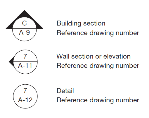
"Reference
Drawing number" means page number for each of your drawing packages. That's where I get the 'D' from in D-0 and D-1 and so on.
 Circles with arrows or triangles on them indicate the point of view of which the object it is referring to is observed. In other words, Imagine you are standing inside the circle and facing the same direction as the arrow.
Section lines cut through objects and indicate which drawing on what page this point of view can be found
Portions of objects like can be circled and then drawn at a much larger scale on a separate page.
Cabinetmakers often circle and draw joints in full scale this way for clarity and reference.
Notes and revisions in the side column should be numbered and referred to with these Symbols
Start by figuring out where to draw a
section line and
section reference on page
D-0 that would illustrate the point of view
Sectional elevation 02 on page
D-1 is.
After you have successfully done this and shown your teacher, go ahead and so the same for
Sectional elevation 03 and sectional plan 01.


Student Ya-Fen Huang has some advice